
Weld on hinges look simple, but their internal load path and welding logic decide whether your equipment door lasts five years or fails in six months.
A weld on hinge works by fixing two barrels to separate steel members through welding, allowing a solid steel pin to act as a fixed rotational axis. The door rotates around this pin while shear force transfers through the pin and bending stress distributes into the weld zone. Proper pin diameter, barrel wall thickness, and weld penetration directly determine torque capacity, fatigue life, and long term alignment stability.
If you design industrial equipment, you need to understand what truly happens inside that rotating barrel.
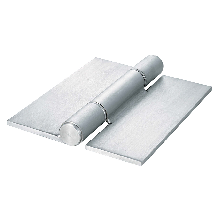
What Is a Weld On Hinge in Industrial Manufacturing
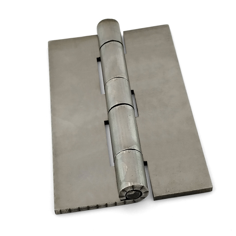
A weld on hinge is a hinge designed to be permanently attached to metal structures through welding rather than fasteners. In industrial fabrication shops, this usually means MIG or TIG welding onto carbon steel or stainless steel frames. Unlike bolted hinges, there is no secondary mechanical fastening to compensate for alignment errors, so positioning accuracy before final weld matters more than most engineers expect.
From my experience, many buyers focus only on door weight and forget weld penetration depth. A hinge can have sufficient pin diameter but still fail because the weld throat is undersized. I have seen weld cracking on equipment access panels simply because the fabricator used intermittent weld beads to save time.
Structural Core Components
The typical structure includes two cylindrical barrels and a solid pin. In weld on bullet hinges, one barrel often contains the pin and the mating barrel slides over it. This male and female structure simplifies installation but demands tight concentricity.
Material choice also affects behavior. For heavy vibration equipment, I often recommend industrial weld on hinges made from medium carbon steel rather than soft low carbon steel. The slight increase in hardness improves wear resistance around the pin bore.
| Component | Function | Common Failure |
|---|---|---|
| Pin | Carries shear load | Galling or bending |
| Barrel | Houses rotation axis | Oval wear |
| Weld zone | Transfers load to frame | Crack initiation |
Core Working Mechanism
At its core, the hinge functions as a single axis rotary joint. The pin resists shear from door weight. The barrel transfers bending moment into the welded structure. When the door opens, torque builds at the hinge line. That torque equals door weight multiplied by distance from hinge axis to center of gravity.
Many engineers underestimate dynamic load. When an operator swings a heavy enclosure door quickly, impact load can exceed static load by two or three times. This is why I often suggest checking hinge weight rating with a safety factor of at least three for industrial access doors.
Load Path Analysis
Shear stress flows through the pin cross section. Bending stress concentrates at the weld toe. If hinge spacing is incorrect, the top hinge may carry up to sixty percent of total load.
In some trailer applications, clients compare with heavy duty trailer ramp hinges, but ramp hinges distribute load differently because they often work in dual axis support. Do not assume equal performance.
How a Bullet Hinge Functions
Bullet hinges use a cylindrical barrel design that visually resembles ammunition. The real advantage is compact geometry with high shear capacity relative to size.
The male portion typically contains the pin. The female portion slides over it and rests on a thrust surface. If that thrust surface is too thin, axial wear develops and vertical play appears within months.
Clearance and Rotation Control
Radial clearance between pin and barrel must balance friction and stability. Too tight and the hinge seizes after welding heat distortion. Too loose and the door develops sag.
I have found that many failures blamed on material are actually caused by weld shrinkage pulling barrels out of alignment. Even heavy duty weld on barrel hinges can bind if tack welding sequence is wrong.
Load Transfer and Stress Distribution
Every weld on hinge is a stress concentrator. The highest stress often appears not inside the barrel but at the weld toe where the hinge meets the door frame.
When using extra heavy duty weld on hinges for large generator enclosures, hinge spacing becomes critical. Increasing the number of hinges reduces individual load but increases alignment complexity. If barrels are not coaxial within tight tolerance, rotational resistance increases sharply.
Bending and Fatigue
Cyclic opening creates fatigue stress. Micro cracks often initiate at weld undercut regions. I recommend full penetration weld for doors above one hundred kilograms, even if design drawings specify fillet weld only.
| Parameter | Design Impact |
|---|---|
| Pin diameter | Shear strength |
| Barrel thickness | Resistance to oval wear |
| Weld size | Load transfer capacity |
| Hinge spacing | Bending distribution |
Installation Process in Fabrication Workshops
Proper installation begins with accurate positioning. Never fully weld one hinge before aligning the second. I always tell fabricators to tack both hinges first, test rotation, then complete welding symmetrically.
Surface cleaning is essential. Oil contamination causes porosity in weld bead, reducing effective cross section. After welding, rotate the door through full cycle to confirm smooth motion before painting.
Many ask how installation compares with other hinge types like heavy duty metal gate hinges. The key difference is that weld on hinges depend entirely on weld integrity. There is no bolt torque to retighten later.
Design Parameters That Influence Performance
Pin diameter selection must correspond to shear load. As a quick engineering estimate, allowable shear stress for mild steel pin can be taken around sixty percent of yield strength.
Material selection also matters in corrosive environments. Stainless steel reduces rust but may gall under load if not lubricated. In high humidity chambers, I sometimes recommend coated carbon steel instead of stainless to avoid cold welding on the pin surface.
Clearance control is another overlooked factor. Excessive clearance increases impact wear. Insufficient clearance leads to binding after thermal expansion.
Lubrication and Maintenance Logic
Some designs include grease fittings. Others are sealed. For high frequency industrial access doors, periodic lubrication significantly extends life.
If environment contains dust or metal particles, open lubrication points may attract contamination. In those cases, sealed structure without grease fitting may perform better.
Regular inspection should focus on vertical play. Early detection of axial wear prevents catastrophic weld failure.
Common Failure Modes in Industrial Use
Door sagging usually indicates either insufficient hinge weight rating or improper hinge spacing. Pin seizure often results from lack of lubrication combined with misalignment.
Weld cracking under vibration is common in mobile equipment. I have seen hinges fail not because they were undersized but because weld length was shorter than specified drawing.
If hinge barrels show uneven wear, alignment during welding was likely incorrect.
Engineering Customization Considerations
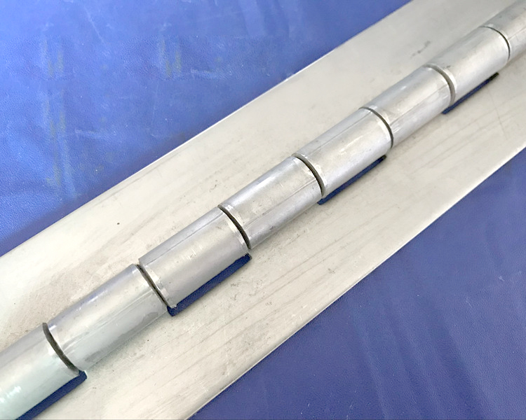
Hinge selection should match door mass, duty cycle, and environment. Removable pin configuration eases maintenance but may reduce axial stability.
For equipment that requires frequent access, consider thicker thrust surfaces and hardened pins. For outdoor machinery, protective coatings or stainless materials are necessary but must be evaluated for galling risk.
If your project requires hinges that cannot be standardized, IHINGES is built for that exact need.
IHINGES is the world’s only manufacturer dedicated exclusively to custom industrial hinges, focusing on real industrial applications rather than off the shelf products.